What is a logic gate?
* Logic gate is an electronic circuit that operates on one or more digital signals to produce an output signal.
A logic gate performs a logical operation such as AND, OR, NOT, etc. on one more logic input (1 or 0) and produces a single logic output (1 or 0). Logic gates process signals which represent "true" or "false". Usually, the positive supply voltage +5 Volts means 'true' and zero (0) Volt represents 'false'.
Logic States Table:
| True | False |
|---|---|
| 1 | 0 |
| High | Low |
| +5 V | 0 V |
| On | Off |
Types of logic Gates:
The manipulation of binary information is done by logic circuits known as logic gates. Different types of logic operations frequently performed in the design of digital systems are: AND, OR, NOT, NAND, NOR, EX-OR, and EX-NOR. An electronic circuit that performs a logic operation is called a logic gate. For example, the electronic circuit which performs OR operation is called OR gate, which serves AND operations is known as AND gate, and so on.
Q: What is a truth table?
A: A truth table is a tabular representation of all possible inputs and corresponding outputs for a logical function or combination of logical functions. It shows the relationship between the inputs and the output(s) of a logic circuit.
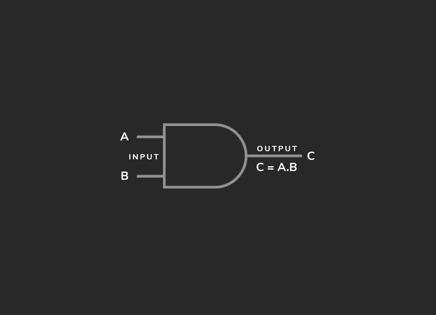
AND Gate:
AND gate has two or more inputs and a single output. An input signal applied to a gate has only two stable states, either input signal applied to a gate has only two stable states, either 1 (high) or 0 (low). The logical operation of the AND gate is such that the output is 1 (high) when all the inputs are 1 (high), otherwise, it is low (0).
Truth Table:
| Input | Output | |
|---|---|---|
| A | B | C = A + B |
| 0 | 0 | 0 |
| 0 | 1 | 0 |
| 1 | 0 | 0 |
| 1 | 1 | 1 |
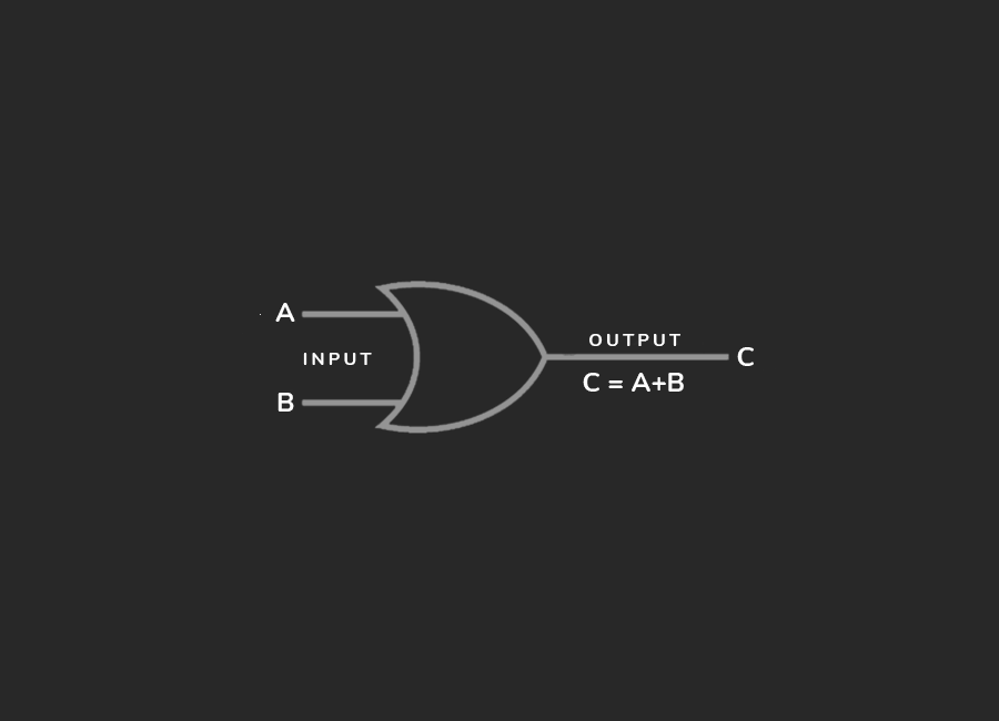
OR Gate:
The OR gate has two or more input signals but only one output signal. If any of the input signals is 1 (true or high) then the output is 1 (true or high). In electronics, we use integrated circuits that are designed to perform the role of OR operator. Such a functional switch is named as OR gate.
Truth Table:
| Input | Output | |
|---|---|---|
| A | B | C = A + B |
| 0 | 0 | 0 |
| 0 | 1 | 1 |
| 1 | 0 | 1 |
| 1 | 1 | 1 |
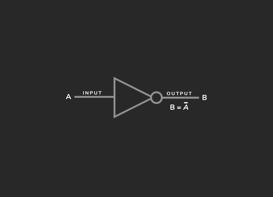
NOT Gate:
NOT gate reverses the input signal value. If the input value is '1', the output value will be '0', then the output value will be '1'. NOT gate also can be called as inverter too.
Truth Table:
| Input | Output |
|---|---|
| A | B |
| 0 | 1 |
| 1 | 0 |
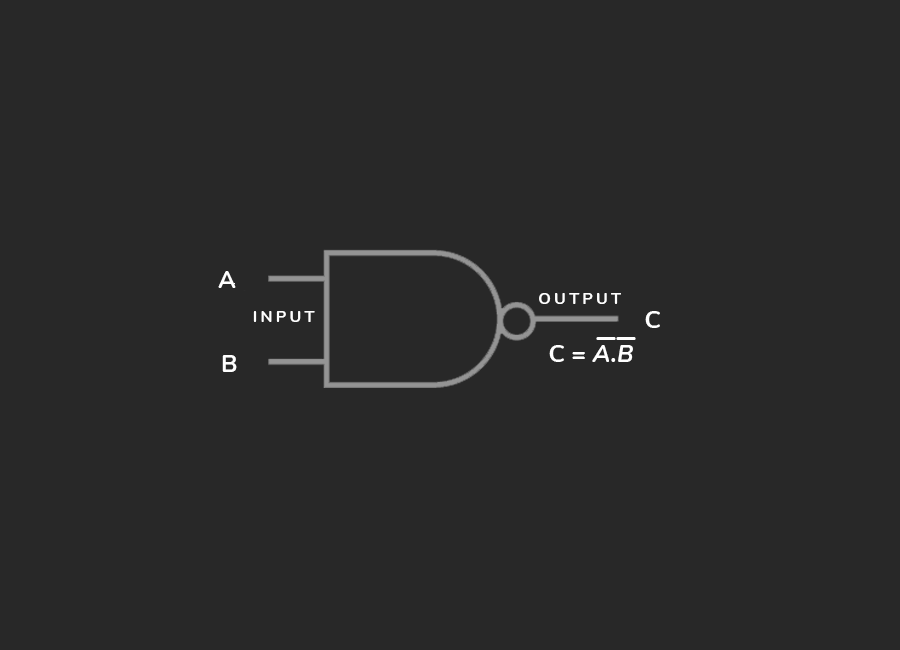
NAND Gate:
NAND gate has two or more inputs and a single output. The NAND function is the complement of AND function. An AND gate can be combined with an Inverter to form a NAND gate. The term NAND is formed by the concatenation NOT-AND and implies an AND function with an inverted output.
Truth Table:
| Input | Output | |
|---|---|---|
| A | B | C = A + B |
| 0 | 0 | 1 |
| 0 | 1 | 1 |
| 1 | 0 | 1 |
| 1 | 1 | 0 |
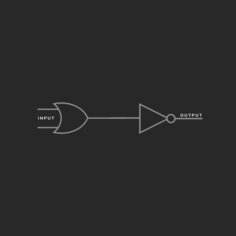
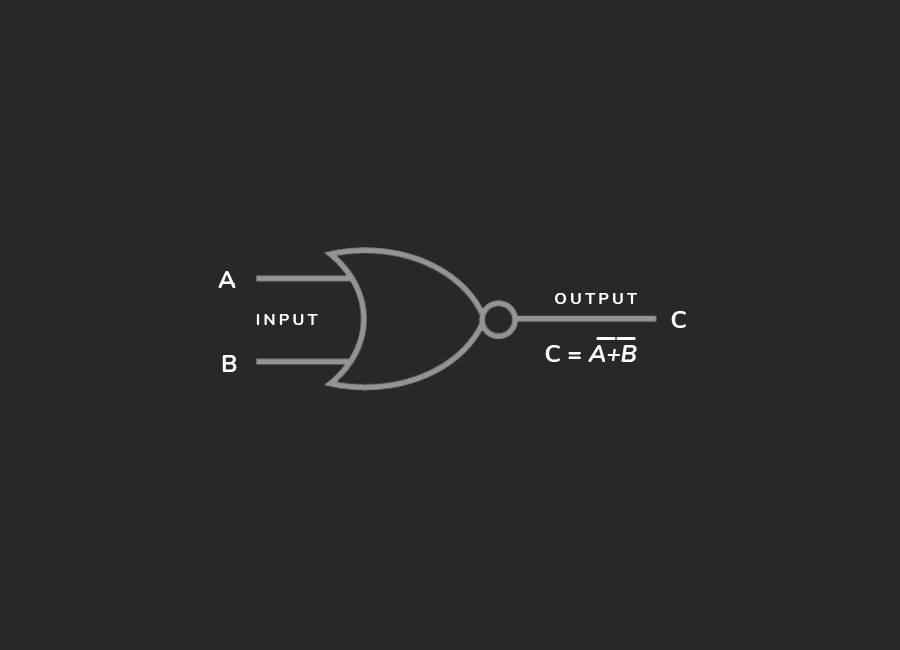
NOR Gate:
The NOR gate has two or more inputs and a single output. The NOR function is the complement of the OR function. An OR gate can be combined with an Inverter to form a NOR gate. The term NOR is formed by the concatenation NOT-OR and implies an OR function with an inverted output.
Truth Table:
| Input | Output | |
|---|---|---|
| A | B | C = A + B |
| 0 | 0 | 1 |
| 0 | 1 | 0 |
| 1 | 0 | 0 |
| 1 | 1 | 0 |
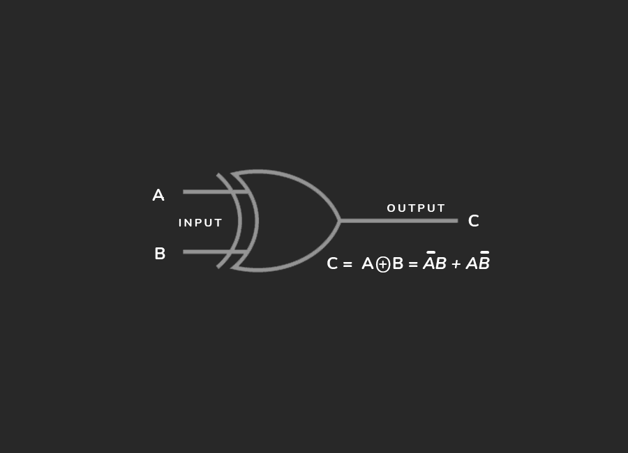
XOR Gate:
XOR is also known as Exclusive-OR. In this logical operator, the output is 1 (true) when both the inputs are of opposite types. If A is true, then B should be false to get an output value of true. When the inputs A and B have the same type of values say true or false, the output is always false. Thus, when both the inputs are the same, the output is 0 or false. When the inputs are of the opposite type, then the output is 1 or more.
Truth Table:
| Input | Output | |
|---|---|---|
| A | B | C = A + B |
| 0 | 0 | 0 |
| 0 | 1 | 1 |
| 1 | 0 | 1 |
| 1 | 1 | 0 |
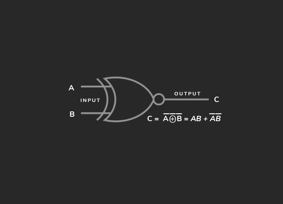
XNOR Gate:
XNOR is also known as Exclusive-NOR. The XNOR gate is logically equivalent to an inverted XOR i.e. XOR gate followed by NOT gate (an inverter). The XNOR gate produces '1' (high) only when the logical voltage of both inputs A and B are the same. The output is '0' when the inputs are of the opposite type.
Truth Table:
| Input | Output | |
|---|---|---|
| A | B | C = A + B |
| 0 | 0 | 1 |
| 0 | 1 | 0 |
| 1 | 0 | 0 |
| 1 | 1 | 1 |
Note: These gates can be combined in various ways to create more complex logical functions, forming the basis of digital circuit design.
What's Next?
We've now entered the finance section on this platform, where you can enhance your financial literacy.